Electric Flexible Anti-Condensation Heaters

Flexible Heaters

Our Anti-Condensation Heaters are required to prevent breakdown or corrosion to Electric Motors by water forming/pooling inside the enclosure. This usually happens in colder temperatures or higher humidity areas. Usually, this damage occurs only when the electric motor is not operational and the internal temperature drops quickly to beneath the dew point. Some typical applications for anti-condensation heaters can include but are not limited to:

  • Shipboard and marine equipment.
  • Dockside/Overhead cranes.
  • Borehole pumps.
  • Electric Motors
  • Generators and Alternators.

Planning for the usage of our ACH at the draft stage of development can save the expense of a costly rewind and complications and unnecessary repairs later!

These heaters are made up of 5 separate heating filaments coated by a protective cover of silicone rubber and then soldered together at the terminals. Next, it is covered by a braided glass fibre sleeve and then wrapped with adhesive tape composed of the same material. Finally, the cold ends are made up with FEP.

These heaters’ unique design makes them ideal for class F and H applications and electric machines being subjected to vibration and shock. In addition, their -60° to + 200° temperature range allows these products to be used even in the harshest environments.

These heaters are fitted around the base of the winding heads before or after impregnation. Please take care to cover at least three-quarters of them. If the element selected is more far-reaching than the outline of the head, do not overlap the ends and leave a gap of at least 5mm to dodge localized overheating.

Some specifications of these AC Heaters are as follows:

  • Temperature range -60°C / + 200°C
  • Dielectric strength 2.5 kV / 10s
  • FEP UL 1330 AWG 20 (200°C / 600V) leads

These AC Heaters are UL Approved.


Guest Article – How do RTD Sensors Work?

Thermocouples – Electric Motor Parts & Accessories Australia​

How Do RTD Sensors Work?


This article will focus on discussing one of our products for thermal protection, the RTD Sensors.


What is an RTD?


RTD sensors or resistance temperature detectors are temperature sensors that measure temperature based on the changes of resistance of metal with temperature. They are also referred to as resistance thermometers. They have sensing elements placed near the area at which the temperature must be measured. They are most used in industrial applications because of their accuracy, repeatability, and ability to withstand harsh environments.


Major Components of RTD Sensors


  • A resistance element is a metal that senses temperature changes. Its length usually ranges from ⅛” to 3”. In most cases, it is platinum because platinum is chemically inert, offers almost linear temperature-resistance relationships, and can sense resistance changes quickly. Other materials used as resistance elements are copper, nickel, iridium, tungsten, and Balco.
  • Wires connect the resistance element to the measuring instrument. The number of wires connecting the resistance element to the measuring instrument varies for different applications. RTD sensors with more wires are known to be more accurate. Two-wire RTD sensors are generally used for applications where approximate temperature values are needed, whereas three-wire RTD sensors are most commonly used in industrial applications. Four-wire RTD sensors are the most accurate of the three-wire configurations of RTD sensors and are used in applications where tougher temperature control is required. For protection, these wires are insulated with Teflon or fiberglass.
  • Tubing materials commonly used for industrial assemblies are stainless steel 316 and Inconel. Stainless steel 316 is suitable for assemblies up to 500 °F. Beyond 500 °F, Inconel 600 is used for tubing materials.
  • Process connections include standard fittings for thermocouples such as compression, welded, and spring-loaded fittings.
  • The outer diameter of an RTD is located just above the resistance element. It ranges from 0.063” to 0.500”.
  • Cold end termination of RTD sensors can be plugs, bare wires, terminal heads, or reference junctions common to thermocouples.


Working Principle of RTD Sensors


RTD sensors are commonly covered with stainless steel or Inconel that protects the sensing element from shocks, vibrations, and other mechanical impacts. These allow them to be placed directly to the area where temperature must be measured. The size and lengths of connecting wires affect temperature readings. Thus, all connecting wires should have similar sizes and lengths to ensure good calibration. The calibration of an RTD sensor is carried out by comparing its resistance values against a standard. On the other hand, the frequency of calibration of RTD sensors depends on the temperature cycle and the environmental and mechanical impacts affecting the RTD sensors.


The working principle of RTD sensors is based on the correlation between metal resistance and temperature. During operations, electric current is transmitted through a piece of metal or the resistance element. Using the metal’s known resistance characteristics, the measured resistance value of the resistance element is then correlated to temperature. The metal resistance to the flow of current increases as the temperature of the metal increases. Electrical resistance is usually expressed in ohms, and resistance elements are commonly specified based on their resistance in ohms at 0 °C.


Applications of RTD Sensors


RTD sensors provide consistent, reliable, and accurate temperature measurements, making them suitable for a wide range of industrial applications. They are used in the automotive industry to measure engine, air, and water temperatures. They are also found in pharmaceutical, chemical, and electronics industries where temperature monitoring and control are of utmost importance. RTD sensors have countless applications. This is all because of their adaptability, flexibility, and reliable performance.

Mec supplies a wide selection of quality electric motor parts, vibration and thermal sensors, and accessories. Since 2004, we have been providing top-quality, customized sensors for our customers.

For more questions about RTD sensors, do not hesitate to contact us!

Author:

John Hamlin

About the Author

John Hamlin is a freelance writer who has a background in engineering. With a keen interest in technology and writing, John has been working online providing insight and direction for many years. His latest work has been on a compilation of industrial manufacturing techniques.

What is an encoder?

Electric Motor Replacement Parts | Repair Parts | Suppliers | Manufacturers | Australia

If you Google encoder, you’ll get a large and bewildering array of responses. For our goals, encoders are used in machinery for movement feedback and motion control.

Continue reading

Vibration Sensors and Accelerometers

Vibration sensors, also identified as piezoelectric sensors, are handy tools for the measurement of multiple processes. Vibration sensors are ideal for measuring the amount and frequency of vibration in machines and equipment.

Continue reading

What is an RTD, and how does it work?

Thermocouples – Electric Motor Parts & Accessories Australia​

A resistance temperature detector is a temperature sensor, also known as an RTD or resistance thermometer. Conductors attach the sensing element to the measurement instrument. Insulation and a protective sheath make up an RTD.

The linear relationship between temperature and resistance make this type of temperature sensor accurate and repeatable. The type of metal used in RTD construction, plus the thermal insulation, can dictate the temperature range at which the RTD can be used. An RTD’s sensing feature is an electrical resistor that changes resistance value as temperature changes. The transition in resistance with temperature occurs predictably.

An RTD’s sensing feature is usually made up of a wire coil or a substrate with a platinum etched film. The electrical resistance can be measured from a distance away from the method or material being measured thanks to extension wires connected to the sensing element. The sensing factor is enclosed in a protective sheath (usually stainless steel). Platinum is the most used material.

There are two main approaches for RTD construction. The most popular process is to insert the RTD part and wires into a metal tube with a closed-end. The tube is filled with a vibration dampening and heat transfer medium, typically alumina powder. The open end is sealed with silicone, epoxy, or ceramic cement.

A mineral insulated metal is an alternative building tool.

A mineral insulated metal sheath (MIMS) cable is an alternative construction process. The RTD element is connected to nickel or copper wires that are insulated with Magnesium Oxide (MgO). This end is also electrically insulated with MgO and welded shut. Before sealing, extension wires are connected to the other end.

Vibration Sensor Offering

MEC’s extensive range of vibration testing technology have which are manufactured to the best quality. MEC products specialise in vibration testing, and the efforts of our experienced team ensure that MEC will find the right solution to fit the application.

Accelerometers

MEC provides a vast range of quality accelerometers, including all top entry, side exit configurations, including dual output and our popular triaxial models. Also Included in our catalogue are all our acceleration, submersible and temperature models. Contact us to discuss our range as well as the typical and potential applications.

Vibration Modular Systems

MEC provides an extensive scope of power supplies, signal conditioning modules, housings and converter cards. You can see our product page, as well as the typical applications.

Switch, Connection and Junction Enclosures

We also supply a complete range of low-cost switch, connection and junction enclosures available in mild or stainless steel and GRP. 

Vibration Meter Kits

Our Vibration Meter Kits are reliable and easy to use hand-held machine condition inspection instruments available on the market. They provide optimum vibration measurement, bearing status check facility and an alarm indication

Cables & Accessories

We also supply access to an extensive range of accelerometer cable assemblies as well as cable assemblies, accelerometer & system integrity checkers, magnets, custom made solutions, and mounting studs.

Vibration Sensors

Vibration sensors or accelerometers are quite often used in condition monitoring applications that require measurement of acceleration, vibration or shocks experienced by the equipment or object. This measure the acceleration in reference to Earth’s gravity. The sensing element of the vibration sensor is electromechanical in nature and behaves as a damped mass attached to a spring, consisting of mechanical sensing elements with mechanisms to transition the mechanical vibration into electrical output. The sensing parts of the commercial accelerometers are usually made up of piezoelectric or capacitive material.
Accelerometers are accessible in an extensive range of models; charge-type piezoelectric or Integrated Electronics Piezo-Electric accelerometers with a broad range of frequency response for universal condition monitoring applications or vibration monitoring, DC-response piezoresistive accelerometer for shock tests, automotive crash tests or blast testing, or very sensitive variable capacitance accelerometers for automotive NHV (Noise, harness, vibration) tests, seismic testing and motion measurement. Vibration sensors can also be mounted on a drone and used as components of the inertia driven navigation assembly.
MEC Australia offers a complete suite of vibration measurement sensors to support almost all industrial and research applications’ condition monitoring program and testing requirements. MEC accelerometers have been widely used in university research laboratories and industries such as defence and military, automotive, manufacturing, mining, aerospace, geotechnical, marine, and oil and gas. Examples of applications are Missiles and ballistic testing, aircraft flight test, seismic monitoring, automotive crash test, vibration monitoring in gas turbines and many others.

Industrial vibration sensor selection Made Easy

Nine Questions to Successfully Name the Solution to Your Application.


Choosing the best accelerometer for a specific predictive maintenance application can be a daunting task – even for the usual experienced walk-around warrior. Sensor manufacturers’ web pages are laden with hundreds, if not thousands, of similar-looking products, all for “monitoring vibration”. The process of selection can typically be refined down to a group of nine appropriate questions. This article will allow you to master the mystery of vibration application engineering. By finding the solutions to the following nine problems, as it applies to your personal application, you will find the best vibration monitoring solution.

What do you want to measure?

This may seem obvious at first, but stop for a second – what are you actually trying to measure? In other words, what are your goals? What are you expecting? What are you going to do with the data? Vibration can be monitored with accelerometers that provide raw vibration data or transmitters, which provide the calculated overall RMS (Root Mean Square) vibration. The raw vibration data is useful to analysts because it contains all the information required. The overall RMS or peak values are helpful to control systems such as PLC, DCS, SCADA, and PI due to a continuous 4-20mA signal. In some applications, customers use both. By determining which of these signals is required for your application, you can significantly narrow your search. Also, are you measuring vibration in acceleration, velocity, or displacement? Have you considered some of today’s industrial sensors are equipped with the ability to output temperature along with vibration? Both ICP (Integrated Circuit Piezoelectric) accelerometers and 4-20 mA transmitters are available with the temperature output option. Lastly, some applications, such as vertical pumps, are ideally monitored in more than one axis of vibration. Does your application recalibration axis-axial, or tri-axial measurement? Comparison of ICP sensor and 4-20 mA transmitter outputs. ICP raw vibration or 4-20 mA transmitter? Are you measuring acceleration, velocity, or displacement? Do you want to measure temperature? Tri-axial, bi-axial, or single axial measurement?

What is the amplitude of vibration?

The maximum amplitude or range of the vibration being measured will determine the range of the sensor that can be used. Typical sensor range ICP accelerometers are 100 mV/g for a standard application and 500 mV/g for a low frequency or low amplitude application. General industrial applications with 4-20 mA transmitters commonly use a range of 0-10mm or 0-25mm.

What is the vibration frequency?

Physical structures and dynamic systems respond diversely to varying excitation frequencies – a vibration sensor is no different. By nature, Piezoelectric materials act as high pass filters and, as a result, even the best piezoelectrics still have a low-frequency limit near 0.2 Hz. At the natural frequency, the signal is greatly amplified, leading to significant change insensitivity and possible saturation. Saturation is caused by exciting sensor resonance, most industrial accelerometers have single or double pole RC filters. It is critical to select a sensor with a usable frequency range that includes all frequencies of vibration you are interested in measuring.

What is the temperature of the environment?

Extremely high-temperature applications can pose a threat to the electronics built into ICP and 4-20 mA transmitters. For very high-temperature applications charge mode accelerometers are available. Charge mode accelerometers do not have built-in electronics like ICP sensors but instead have remotely located charge amplifiers. For ultra-high temperature applications above 260° Celcius.

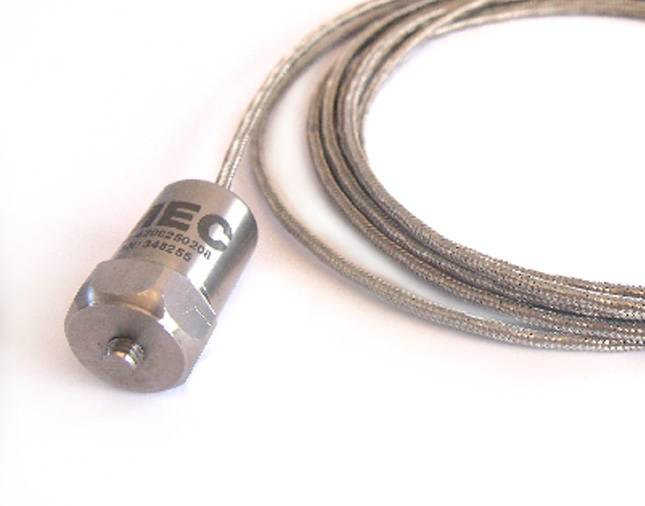
For applications such as gas turbine vibration monitoring, charge mode accelerometers with integral hard-line cable are available. 

Will the sensor be submerged in liquid?

MEC’s industrial accelerometers with integral polyurethane cables are completely submersible in liquid, (for permanent installation) to depths corresponding to 1000 PSI. For high-pressure applications, it is recommended to pressure test the sensors at pressure for one hour. Applications requiring complete submersion will need integral cable. If the application is not completely submersed but sprayed, (such as cutting fluid on machine tools), integral cable is normally required. 

Will it be exposed to potentially harmful chemicals or debris?

MEC’s industrial accelerometers are constructed with stainless steel bodies to be corrosion and chemical resistant. If your application is located in an environment with harmful chemicals, consider using PTFE cable with corrosion-resistant boot connectors. It is strongly recommended to check a chemical compatibility chart for any suspect chemicals. For cables that may come into contact with debris such as cutting chips or workers’ tools, integral armour jacketed cables offer excellent protection armour jacketed cable immersed in cutting oil. 

Do you prefer a side exit, top exit, or a low profile sensor?

You will need space to install the sensor on your equipment, is the space available? Sensors are available with top and side exit connectors or integral cables. The geometry of the sensor has little impact on its performance. Still, issues such as space should be considered.

Should you use a precision or low-cost sensor?

There are two main differences between low cost and precision accelerometers. First, precision accelerometers typically receive a full calibration; the sensitivity response is plotted concerning the usable frequency range. Low-cost accelerometers receive a single point calibration; the sensitivity is shown only at a single frequency. Second, precision accelerometers have tighter tolerances on some specifications such as sensitivity and frequency ranges. For example, a precision accelerometer may have a nominal sensitivity of 100 mV/g ± 5% (95-105mV/g).

In comparison, a low-cost accelerometer may have a sensitivity of 100 mV/g ± 10% (90- 110mV/g). Customers with data acquisition systems will often normalize the inputs concerning the actual calibrated sensitivity. This allows a group of low-cost sensors to provide very accurate, repeatable data. Regarding frequency, a precision accelerometer will typically publish frequency ranges where the maximum deviation is 5%. In contrast, low-cost sensors may only publish a 3 dB frequency band. 


Do you need any special approvals?

Accelerometers and 4-20 mA transmitters are available with IECEx and ATEX approvals for use in hazardous areas. The type of approval needed should be compared with the published approvals for that sensor to ensure it meets your requirements. 

By answering the above nine questions, you can greatly narrow your search to the best solution for your application. Keep in mind, some combination of answers may be mutually exclusive, that is a solution for all criteria does not exist. For example, a particular model may not carry the proper ATEX certification for your hazardous area application.

Additionally, very specialized applications may have other considerations than those listed above.

 If you have any questions about your application, please do not hesitate to contact a MEC team member

Most typical reasons for machine vibration

Vibration Sensors World-famous Mind-blowing Quality

Vibration is commonly a back & forth movement, or oscillation, of machines & components in motor-powered equipment. Vibration in industrial equipment can be a sign, or cause, of a problem, or it can be connected with normal operation.

For example, oscillating sanders & vibratory tumblers rely on vibration to function. Internal combustion engines & gear drives, on the other hand, encounter a certain amount of unavoidable vibration.

In general, mechanical equipment is engineered to avoid vibration rather than create it. This article focuses on equipment engineered to evade vibration.

Vibration can mean a problem, & if left unchecked can cause breakage or hastened deterioration of the machinery.

Electric motor vibration can be caused by one or more circumstances at any given time, the most common being imbalance, misalignment, wear & looseness.

  • Unevenness – A “heavy spot” in a rotating part will cause a vibration when the unbalanced weight revolves around the machine’s axis, generating a centrifugal force. The imbalance could be produced by manufacturing faults (machining errors, casting flaws) or maintenance problems (deformed or dirty fan blades, missing balance weights). As machine speed increases, the consequences of imbalance become more prominent. Imbalance can seriously reduce bearing life as well as cause excessive machine vibration.
  • Misalignment /shaft runout – Vibration can occur when machine shafts are out of line. Angular misalignment happens when the axes of (for example) a motor & pump are not equal. When the axes are parallel but not precisely aligned, the condition is known as parallel misalignment. Misalignment can be caused through assembly or develop over time, due to thermal expansion, components shifting or incorrect reassembly after maintenance. The vibration can be radial or axial (in line with the axis of the machine) or both.
  • Wear – As parts such as a ball or roller bearings, drive belts or gears grow worn, they might cause motor vibration. When a roller bearing race has pitted, for example, the bearing rollers will create a vibration each time they travel over the broken area. A gear tooth that is majorly chipped or worn, or a drive belt that is breaking down, can also create vibration.
  • Looseness – Vibration that might otherwise go overlooked can become obvious & destructive if the part that is vibrating has loose bearings or is loosely connected to its mounts. Such looseness might or might not be produced by the underlying vibration. Whatever its cause, looseness can provide any vibration present to cause damage, such as additional bearing wear, wear & fatigue in gear mounts & other parts.

Vibration effects

Vibration can hasten machine wear, drain excess power, & cause equipment to be driven out of service, resulting in unplanned downtime. Other results of vibration include safety issues & diminished working conditions. When measured & investigated properly, however, vibration can play a significant role in preventive maintenance plans. It can serve as an indicator of machine condition & allow plant maintenance experts to act before damage or accident strike.

Consider these variables when examining vibration:

  • Direction, such as radial or axial
  • Amplitude, severity
  • Frequency, shown in cycles per minute (CPM) or Hertz (Hz)—one Hz equals one second or 60 CPM

Plant maintenance specialists need to be able to distinguish between normal & unusual vibration. A good perception of vibration basics & the right tool is all a plant maintenance technician requires to quickly & reliably get to the root of vibration-related issues, including discovering the root cause & severity, then discovering the need for service or repair.

Vibration Sensors & Testers

Vibration sensors & software are typically created for monitoring machine condition over the long term & require special training.

Many industrial maintenance teams work with strict limits on their budgets & time; the sources required for the training & implementation connected with long-term vibration analysis applications may simply be out of reach.

This is where our vibration sensors step in, and one reason why it is such a valuable tool.
Click here to see our quality vibration sensor products.

Our Vibration Sensors are designed to help maintenance professionals discover machine condition & get to the original cause of any problems swiftly.

It fills the gap that exists among high-end, complex vibration analysers & low-end vibration pens, which decrease accuracy for cost & ease of use.

Our electric motor vibration sensors offer the diagnostic capacities of the higher-end analysers along with the speed & suitability of the lower-end testers, at a sensible price.

Plant maintenance technicians need complete diagnostic & problem-solving tools to recognise problems, suggest repairs & give context-sensitive guidance & tips in real-time.

The precision of our vibration sensors allows maintenance crews to act when required to keep mechanical equipment in peak form & to keep equipment productive.

Further reading

Motor Vibration Analysis: Keeping it Simple

Vibration Sensors world-famous mind-blowing quality

Vibration Sensors World-famous Mind-blowing Quality

Vibration Sensors will further solve unnecessary downtime, as well as machine damage which in the long run could end in financial loss.

Vibration Sensors

What are the typical types of vibration sensors & in short, how to pick a vibration sensor?

Definition is Vibration

Firstly, we will explain vibration. Vibration, in short, is a mechanical oscillation encompassing an equilibrium position of a machine; part or merely the back-and-forth motion of a machine & or component.

Where Do You Use Vibrations Sensors?

Ordinarily speaking, vibration in industrial equipment is quite common. However, it can also be a signal of a significant problem.

In machine condition monitoring, we’re dealing with 2 types of vibration, axial (also known as thrust) and radial vibration.

To be specific, axial vibration is a parallel shafting vibration which runs beside the shaft of a motor.

For example, a shaft misalignment could create axial vibration. Radial vibration will happen as a force applied out from the shaft.

There’ll be Radial vibration if the motor is unbalanced; for instance, this will happen if there is a faulty fan blade as well as a bent shaft. Let us now discuss the types of sensors to monitor these kinds of vibration.

Accelerometers

Let’s chat about an Industrial accelerometer. Accelerometers are instruments or field sensors that measure velocity & acceleration of oscillation of a structure.

It will have a transducer that transforms mechanical force, caused by vibration or a shift in motion, into an electrical charge using the Piezoelectric effect.

There are 2 types of Piezoelectric accelerometers: high impedance & low impedance.

High impedance

accelerometers send a signal straight to your measurement instrument. You will find these in laboratories or high-temperature applications.

Low impedance accelerometers have a charge transducer at its front end.

Also as a built-in microcircuit that will transform that charge into a low impedance voltage, this type of sensor easily will interface with conventional instrumentation, which will make it often used in the industry.

Install these permanently if there is a high-risk application.

Contact us

Contact our technical department at GlobalMec, & they will be happy to answer any questions & advise you on the correct sensor for your application.